Building a Band-pass Filter for A Local Oscillator
NanoVNA connected to filter
I have previously built a Colpitts oscillator whose output contained significant harmonic content. Instead of trying to improve the oscillator circuit, I have opted to build a band-pass filter to mitigate these harmonics from the ocillator output.
I used the Marki Microwave LC Filter Design Tool to design the filter. The pass-band I am targeting is roughly from 6.545 to 6.945 MHz, but more importantly, I want significant attenuation (roughly -30 dB) of the second harmonic that is around 12-14 MHz.
Since I only have a limited set of NP0 capacitor values on hand (10, 22, 47,
68, 100, 220, and 330 pF), I had to carefully adjust the filter designer
settings until it generated something that I would be able to build. I found
that opening up the pass-band and trying different values for Direct Coupled Inductor Value allowed me to fine-tune the capacitor values.

Screenshot of filter design tool.
Construction
To build the filter, I used a piece of copper-clad FR4 and some MeSQUARES from QRPme. Input and output ports use U.FL connectors. The inductors used are T37-2 toroids with 27 turns. All capacitors are NP0 for temperature stability.

Contstructed band-pass filter circuit.
Testing
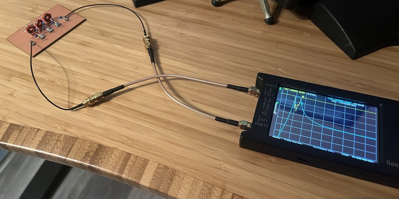
To test the filter, I used a NanoVNA network analyzer to check the filter response.

Vector network analyzer view of the filter response. Blue line shows attenuation by frequency. Actual pass-band is roughly 6 MHz to 7.1 MHz.
Next, I used an oscilloscope and a spectrum analyzer to compare the output of oscillator with and without the filter.

Oscilloscope capture of the very ugly unfiltered output of the oscillator.

Spectrum analyzer view of the unfiltered oscillator. Second harmonic is only -13 dB of the main LO frequency.

Oscilloscope capture of filtered waveform. Harmonics are no longer evident in the time domain. Note: There was no 50 Ohm termination here, so the amplitude does not correspond to power.

Spectrum analyzer view of the filtered oscillator. Second harmonic is now -53 dB of the main LO frequency.